
The IPPC and BvT are directives that you also have to deal with when emitting a spring safety, too. The IPPC Directive, or Directive 1996/61/EC stands for Integrated Pollution Prevention and Control, i.e. the integrated prevention and control of pollution. This directive is part of European environmental law and is based on a number of principles:
Integrated Approach
An integrated approach means that the permit covers everything related to the company concerning the environment, including air, water, and soil emissions, waste generation, use of raw materials, energy efficiency, noise, accident prevention, and site restoration after closure. The ultimate goal is to achieve a high level of environmental protection.
Flexibility
The IPPC directive contains elements of flexibility so that local authorities can adjust the permit conditions to local circumstances, for example:
- The technical characteristics of the installations
- The geographical location
- The local environmental factors
Public Participation
The directive ensures that the public has the right to participate. They are involved in the decision-making process and informed about the consequences of the decision. The public has access to:
- The permit applications
- The permit itself
- The monitored emitted substances
Application of Best Available Techniques (BAT)
The permit conditions (including emission limit values) of the IPPC directive are based on the best available techniques (BAT), which include:
- The applied techniques
- Design, construction, and dismantling of an installation
- Maintenance and operation of an installation
Since January 2013, BAT conclusions and ministerially designated information documents must be taken into account when determining BAT. The permit applicant is required to be aware of the best available techniques and applicable regulations. If no BAT conclusions or information documents apply to an activity or type of production process, or if these do not cover all possible environmental effects of the activity or process, the competent authority must determine the BAT itself.
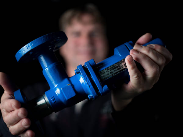
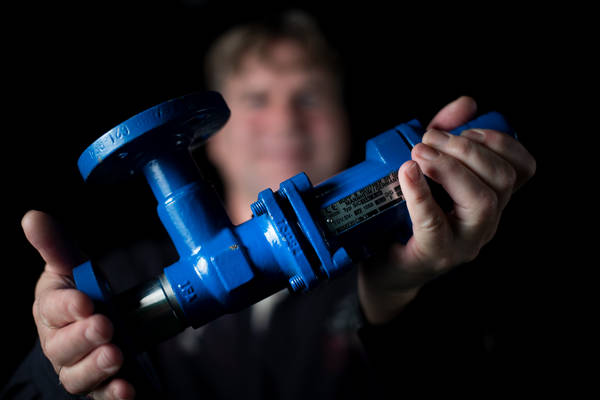
Also, when using safety relief valves, it is important to know what the best available technique is and how to minimize emissions. Although there haven't been many changes in the operating principle of safety valves over the decades, the operation can now be visualized much better, and testing methods have been further developed.
Leakage Test
Safety valves are tested for leakage using the medium with which they are set. In practice, this is usually water or air:
Air: A soap bubble (Nekal bubble) is placed on the outlet/side. In the case of a small safety valve, this is done with a reducer flange. In the case of a large safety valve and when testing according to the API 527 guideline, a counter flange with a tube is mounted on the outlet of the safety valve, which is submerged in a water bath.
Water: The outlet part of the valve is dried with air, and it is observed whether water seeps through the valve seat.
If the test shows that there is excessive leakage, the following causes can be considered:
- Misalignment/perpendicular misalignment of the seat and the disc.
- Quality and tolerances of the product
- Poorly chosen spring or incorrectly set spring pressure
- Debris between the seat and disc after opening
- Damage to the seating surfaces due to transport or opening/closing
- Incorrect choice of seat, disc material, or corrosive medium.
Due to the risks associated with opening/closing the safety valve, we find that many companies in practice choose to replace and/or overhaul the safety valve after a single opening. The rise of digitalization and DCS (Distributed Control System) makes it easier to monitor the operation of safety valves than to perform the above leakage tests and potentially unnecessarily replace or overhaul the valves. With DCS, a sensor is placed in the cap or a pressure measurement is applied. The advantage of the pressure measurement is that it indicates whether the safety valve needs to be replaced.
Production techniques are now more precise, and safety valves can be made from more and better materials than before. Consider, for example, the spring material. By applying the latest techniques, such as a bellows seal, emission levels in safety valves are reduced. You can also place a rupture disc in front of the safety valve to improve safety and limit emissions. Dick Verhoef, our rupture disc specialist, has previously written a blog about this.
The information for the BAT on safety valves is laid down in various American and European standards that partly determine the implementation and technique, known under the ASME and EN ISO 4126 standards. I will elaborate on this in a future blog.


